

An AX BX CX matrix tray enquiry starts with an important question: what do AX, BX and CX actually mean? These labels may refer to a tray designation, a large-tray handling format or coordinates used by automated equipment. At SuperPak, we recommend verifying the original designation before selecting dimensions, materials or pocket configurations.
This distinction matters in a growing semiconductor industry. According to 2025 global semiconductor market data, sales reached US$795.6 billion, representing 26.2% year-on-year growth.
Quick Summary
An AX BX CX matrix tray search concerns a component carrier with pockets arranged in rows and columns, as described in international matrix-tray specifications. However, AX, BX and CX do not automatically denote three standard tray sizes: Bx appears in large JEDEC-tray specifications, while A/B/C can describe automation reference points. Use a matrix tray to position parts for transport or automated picking. Before selection, confirm the code source, controlled drawing, pocket fit, equipment interface and ESD requirements.
At SuperPak, we recommend three initial checks:
- Identify the terminology. Determine whether AX/BX/CX appears in a tray drawing, purchase record, component specification or machine interface.
- Confirm physical compatibility. Review external dimensions, pocket geometry, orientation, stacking and automated-handling requirements.
- Validate material performance. Establish the required ESD protection, temperature resistance, cleanliness and qualification criteria.
The key principle is simple: verify the designation first, then engineer the tray around the actual component and process.
What Is a Matrix Tray and How Does It Work?
A matrix tray is a component carrier with individual pockets arranged in defined rows and columns. It is designed to locate and support electronic components during handling, testing, storage, transport and automated placement operations, consistent with the applications addressed by IEC 60286-5:2018.
Each pocket is designed around the component’s geometry and permitted contact areas. The pocket arrangement allows a manual operator or automated system to identify individual component positions without searching through randomly oriented parts.
A typical matrix-tray design includes:
- Individual pockets: Cavities that position and support each component.
- Row and column arrangement: A repeatable layout of component locations.
- Pocket pitch: The distance between corresponding points in neighbouring pockets.
- Orientation features: Geometric references used to identify the intended tray or component orientation.
- Stacking features: Surfaces that control how trays sit together.
- Handling interfaces: Areas used by operators, automated loaders, sensors or robotic equipment.
Matrix trays are used for various electronic package types, and IEC 60286-5:2018 provides design rules and common tray characteristics for automatic component handling.
At SuperPak, we approach matrix-tray design as part of the complete component-handling process. The tray needs to accommodate the device while remaining compatible with the equipment and operating conditions that will handle it.
Our thermoformed packaging capabilities support customised packaging designs for semiconductor, electronics and other industrial applications.
The regional manufacturing environment reinforces the need for careful specification. In 2025, semiconductor sales in the Asia Pacific and All Others market category increased by 45.4% compared with 2024. This market growth does not prove increased demand for any particular tray design, but it provides context for the production systems these trays support.

What Do AX, BX and CX Mean on a Matrix Tray?
AX, BX and CX should not automatically be interpreted as three internationally standardised matrix-tray sizes. Their meaning must be established from the document or equipment interface in which they appear.
This distinction is especially important because Bx is used in published large JEDEC-tray interface specifications, while certain automated tray-feeder systems use coordinate references such as BX and CX. These applications describe different things.
A useful starting point is to separate verified meanings from labels that require further investigation.
| Designation | Possible interpretation | Can the tray size be determined from the label alone? | What to check |
| AX | Customer-specific identifier, drawing variation or equipment parameter | No | Original drawing, code legend or equipment manual |
| BX / Bx | Potential reference to a Bx large JEDEC-tray format or another application-specific code | No | Applicable design registration, drawing revision and equipment interface |
| CX | Customer-specific identifier, drawing variation or equipment parameter | No | Approved specification or machine documentation |
| A/B/C reference points | Positions used to establish a tray coordinate system in some automated equipment | No | Equipment-specific coordinate definitions and setup instructions |
The documented Bx large-tray format and A/B/C coordinate examples are supported by separate published technical references. Neither establishes AX, BX and CX as a universal three-category size system.
Does BX Always Mean a Bx Large JEDEC Tray?
No. Bx is a documented designation for large trays in the scope of SEMI E200, but an uppercase BX label on a purchase order or equipment display does not prove that the physical tray follows the applicable registered design.
The SEMI E200-0626 specification defines a load-port interface for single Bx large trays or stacks associated with JEDEC DR4.10. Its scope concerns the physical transfer interface between trays or tray stacks and processing equipment.
Before treating BX as a large-tray designation, we recommend confirming:
- The full tray part number and engineering drawing.
- The applicable JEDEC design registration.
- The required drawing revision.
- The tray’s actual external and stacking dimensions.
- The equipment interface that will receive the tray.
A similar label is not proof of dimensional compatibility.
Could AX, BX and CX Refer to Machine Coordinates?
Yes, the designation may relate to an automated tray coordinate system, although the meaning must be confirmed for the specific equipment. Some documented tray-feeder software uses reference points A, B and C, including BX and CX coordinate fields, to establish component positions within a matrix.
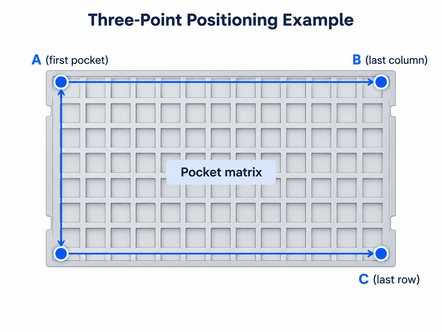
In the documented tray-feeder example, A is the starting point, B establishes the horizontal direction and C helps establish the vertical direction of the matrix. The equipment also uses row and column counts to calculate component positions.
This does not establish AX as a universal coordinate field. We would need the actual machine screen or manual before interpreting the complete AX/BX/CX sequence.
Which Matrix-Tray Standards Apply in 2026?
The applicable matrix-tray standard depends on whether the requirement concerns physical tray geometry, a registered handling interface or ESD-protective packaging performance. IEC matrix-tray requirements, JEDEC design registrations and SEMI equipment-interface specifications address related but distinct technical requirements.
In our specification reviews, we recommend identifying the applicable publication and revision before discussing whether a tray is standard-compliant.
| Standard or document | What it addresses | What it does not automatically establish | Required verification |
| IEC 60286-5:2018 | Common dimensions, tolerances and design characteristics of matrix trays for automatic handling | That every pocketed tray qualifies as standard | Compare the controlled drawing with applicable design rules |
| JEDEC DR-4.10G:2026 | Generic shipping and handling matrix-tray design registration | That a tray with a similar name or appearance matches the design | Confirm the correct registration and drawing revision |
| SEMI E200-0626 | Load-port requirements for Bx large-tray handling | Compatibility of every oversized or custom tray | Verify the specified Bx interface and equipment |
| IEC 61340-5-3:2022 | Required properties and classifications of ESD-protective packaging | Tray geometry or automation compatibility | Verify protective properties and referenced testing |
| ANSI/ESD S541-2026 | ESD-protective packaging material requirements | Suitability for every temperature or cleaning process | Confirm the relevant ESD control and test requirements |
Each document has a defined application. For example, the IEC matrix-tray standard describes common tray dimensions and characteristics, while the SEMI large-tray load-port specification addresses equipment transfer interfaces.
For applications involving oversized components or new pocket configurations, our guide to specifying a customised large JEDEC tray explains the distinction between preserving an established outer interface and developing a custom large-format solution.
Is the 2025 JEDEC Matrix-Tray Revision Still Current?
No. As of October 2026, JEDEC DR-4.10G:2026 is listed as the current generic shipping and handling matrix-tray design registration, superseding JEDEC DR-4.10F:2025.
The newer revision should be reviewed when preparing new specifications. However, an existing qualified production line may still operate under a customer-approved drawing based on an earlier revision.
For that reason, we recommend documenting both the current standards revision and the revision contractually required for the application. Any proposed migration should pass through the customer’s engineering change-control and qualification process.
What Information Is Needed to Identify an AX/BX/CX Tray?
The most reliable way to identify an AX/BX/CX matrix tray is to obtain its original designation and at least one controlled technical reference. A complete tray part number, approved drawing, representative sample or equipment specification gives us a stronger basis for identification than the letters alone.
At SuperPak, we would begin with a structured identification review. Our part-fit analysis and simulation services support engineering assessments of packaging fit and functionality.
Matrix-tray identification checklist
| Required information | What to provide | Status to record |
| AX/BX/CX designation | Exact spelling and where the label appears | Known / Unknown |
| Original reference | Drawing, machine manual, purchase record or label photograph | Available / Required |
| Part identification | Tray part number, component number and drawing revision | Verified / Unverified |
| Tray dimensions | External length, width, height and stacking features | Measured / Pending |
| Pocket configuration | Rows, columns, pitch, pocket size and orientation | Verified / Pending |
| Component information | Drawing, tolerances, weight and restricted-contact areas | Complete / Incomplete |
| Equipment | Loader, robot, rack, oven or other applicable equipment model | Confirmed / Pending |
| Material requirements | ESD, temperature, cleanliness and reuse requirements | Defined / To confirm |
| Application | Replacement tray, redesign or new packaging project | Confirmed / Pending |
Photographs should show the complete tray, orientation features, visible part markings and close-up pocket geometry. If the tray is being replaced, a physical sample can help resolve differences between an old drawing and the actual supplied item.
For a new design, we also ask which component surfaces may safely contact the tray. This question helps prevent an apparently suitable pocket from supporting the component at an unacceptable location.
If only the AX/BX/CX code is available, we would record the designation as unverified until supporting information establishes its meaning.
Contact Superpak: If you are unsure what an AX, BX or CX tray code refers to, Contact Superpak and share the existing tray drawing, part number or photographs for an initial technical review.
How Do You Specify the Correct Matrix Tray Step by Step?
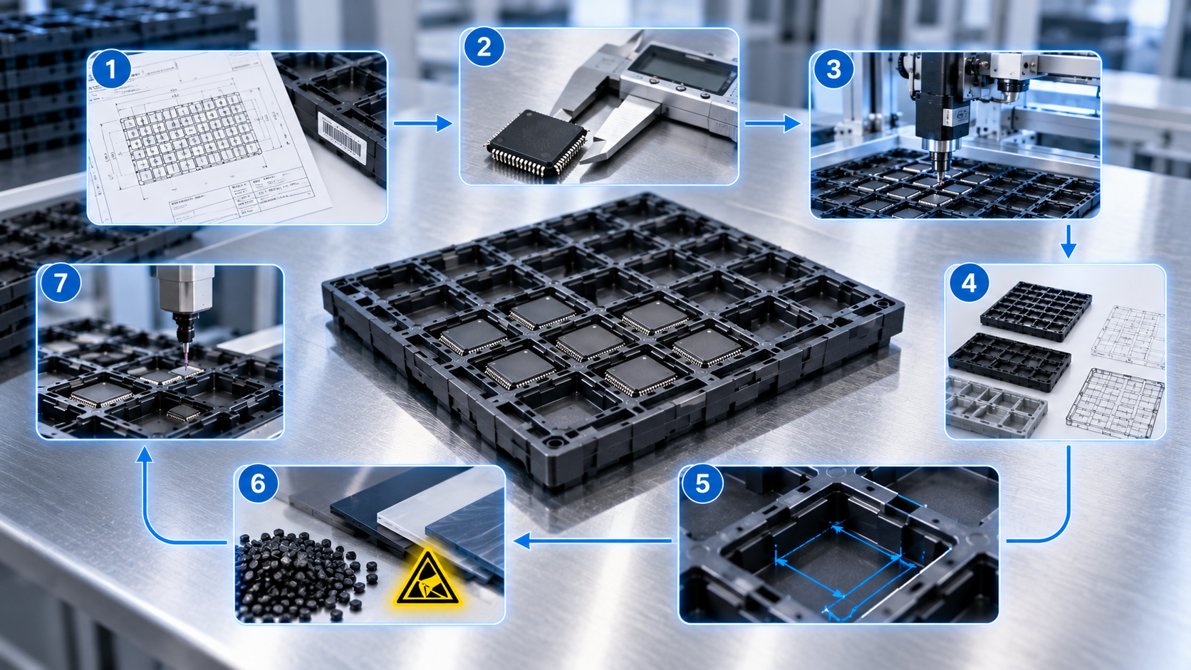
A matrix tray should be specified by identifying the component, process route and equipment interface before finalising pocket geometry or material. We recommend a seven-step workflow that links each design decision to a controlled input and a verifiable output.
This approach is particularly relevant to regional electronics manufacturing. According to the Singapore Economic Development Board, Singapore accounted for approximately one in 10 chips and one in five semiconductor equipment units produced worldwide in 2026. These figures describe the manufacturing ecosystem, not the performance or compatibility of any individual tray.
Our Design Center provides conceptual design and material-selection support for customised packaging applications.
Step 1: Identify the code’s origin
Start by tracing AX, BX or CX to its original document. Check whether it is a tray-design reference, customer part number, machine coordinate or internal purchasing code.
- Input: Original label, drawing or equipment screen.
- Decision: What does the code actually identify?
- Output: Verified designation and controlling reference document.
Do not proceed with assumptions about tray dimensions while the code’s meaning remains unresolved.
Step 2: Collect component data
Obtain the component drawing, maximum dimensional envelope, tolerance limits and physical characteristics. Identify protruding leads, connectors, sensitive surfaces and permitted support areas.
- Input: Approved component drawing, CAD model and representative samples.
- Decision: Which surfaces may be supported, and how much clearance is required?
- Output: Component envelope and contact-zone specification.
The maximum component dimensions and their relevant tolerances should determine the fit analysis rather than a single nominal sample.
Step 3: Map the complete handling process
Record every process in which the tray will be loaded, moved, stored or emptied. Include both automated and manual operations, as well as any exposure to heat, cleaning or transport conditions.
- Input: Process flow, equipment models and operating conditions.
- Decision: Which interfaces and environmental limits control the design?
- Output: Equipment and process compatibility matrix.
A tray that works at the loading station must also work at every required downstream interface.
Step 4: Choose the tray architecture
Determine whether the project can retain a recognised external tray interface or requires another format. Options may include standard-format trays, custom pockets within an established interface, a verified Bx large-tray design or a fully custom footprint.
- Input: Component envelope and equipment-interface requirements.
- Decision: Which architecture satisfies the controlling constraints?
- Output: Approved preliminary tray concept.
Record any assumptions that must be tested before the design can be accepted.
Step 5: Define the pocket matrix
Specify the pocket arrangement, row and column counts, X/Y pitch, orientation references, support zones, handling access and stacking geometry.
- Input: Component model, tray architecture and equipment requirements.
- Decision: How should components be located, supported and removed?
- Output: Preliminary dimensioned tray drawing.
The design should also define which dimensions are critical to equipment operation and which are controlled by the customer-specific pocket design.
Step 6: Establish material and environmental requirements
Identify the required ESD properties, thermal exposure, mechanical performance, cleanliness and intended reuse conditions. Determine the supporting material data and tests needed.
- Input: ESD control requirements, process profile and environmental conditions.
- Decision: Which material properties must be demonstrated?
- Output: Material specification and qualification requirements.
The IEC 61340-5-3:2022 standard provides requirements and referenced methods for evaluating ESD-protective packaging properties. These requirements should be applied according to the intended use and the component’s sensitivity.
Step 7: Prototype, validate and approve
Evaluate representative trays using dimensional inspection, component-fit assessment and relevant handling trials. Include loaded-stack checks and environmental testing where applicable.
- Input: Prototype trays, approved drawings and acceptance criteria.
- Decision: Does the design satisfy every critical requirement?
- Output: Documented qualification results and an approved production baseline.
A design should proceed to production only when the relevant acceptance criteria have been met or deviations have been formally resolved.
How Do Standard, Bx and Custom Matrix Trays Compare?
The main difference between standard-format, Bx large-tray and custom matrix-tray approaches is the interface being controlled and the flexibility available for component-specific design. A customised pocket arrangement may preserve an existing handling format, whereas a fully custom external footprint generally requires broader equipment qualification.
This distinction matters as semiconductor equipment becomes more complex. According to 2026 semiconductor equipment market research, assembly and packaging equipment sales increased by 20.8% in 2025, while semiconductor test equipment sales rose by 55.3%. These are equipment-market growth figures, not measured improvements in tray performance.
| Tray approach | External interface | Internal design flexibility | Main verification required | When to consider it |
| Standard-format matrix tray | Controlled by the applicable recognised design | Limited by its applicable design requirements | Drawing revision, dimensions, stacking and handler compatibility | An existing qualified handling format is required |
| Custom pockets with retained outer interface | Intended to preserve an approved handling outline | Component-specific pockets, support surfaces and relief features | Pocket fit, dimensional tolerances, stacking and pickup access | A new component must use existing tray-handling equipment |
| Bx large-tray system | Applicable Bx design and large-tray equipment interface | Depends on the approved registered drawing | Bx format, load port, tray stack and equipment integration | A verified large-tray handling system is required |
| Fully custom matrix tray | Customer-defined geometry and handling interfaces | Outer footprint, pockets and stacking features can be redesigned | Complete equipment, process, material and logistics qualification | Existing formats cannot meet the component or process requirements |
For a practical selection, we recommend answering three questions:
- Must the tray operate with existing standard-format or Bx equipment?
- Can the component fit safely within the usable internal design area?
- Can the required support, handling and material properties be achieved without changing the external interface?
If all three answers are supported by engineering evidence, retaining the qualified interface may be appropriate. Otherwise, an alternative approved architecture or custom tray design should be investigated.
Which Matrix-Tray Dimensions and Handling Features Matter?
Matrix-tray compatibility depends on the external dimensions, internal pocket geometry, stacking features and positioning references required by the handling system. Dimensions must be evaluated together because a tray may fit the component but fail to stack, load or present the component correctly. These considerations are covered by the common dimensions and handling characteristics described in IEC 60286-5:2018.
The following dimensional information should be included in the engineering drawing.
| Feature | Definition | Why we check it |
| External length and width | Overall tray footprint | Equipment, rack and transport compatibility |
| Tray height | Overall vertical dimension | Loading, handling and storage clearances |
| Pocket length and width | Internal cavity dimensions | Component fit and permitted movement |
| Pocket depth | Vertical space supporting the component | Component height and contact clearance |
| X/Y pitch | Distance between corresponding pocket locations | Automated pickup accuracy |
| Row and column count | Number of pocket positions in each direction | Equipment programming and tray capacity |
| Orientation datum | Reference for component and tray direction | Correct loading and pickup orientation |
| Stacking interface | Features that locate adjacent trays | Stack stability and loaded-component clearance |
| Flatness and warpage | Permitted deviation from the intended geometry | Positioning, sensing and handling reliability |
These characteristics are consistent with the dimensional and handling considerations described in IEC 60286-5:2018. Actual limits must be taken from the relevant controlled tray specification.
As published in our thermoforming specifications, SuperPak has a maximum forming area of 600 mm wide by 1,200 mm long by 400 mm high, with formable sheet thicknesses from 0.16 mm to 10 mm. These are manufacturing capability figures, not guaranteed finished matrix-tray dimensions or proof of JEDEC compatibility.
How Should Pocket Clearance and Support Areas Be Checked?
Pocket clearance should be evaluated against the component’s maximum dimensional envelope, acceptable movement and permitted support surfaces. Increasing clearance without checking component stability can introduce positioning problems.
We recommend assessing the component and pocket together rather than designing from nominal dimensions alone.
The review should confirm:
- Maximum component dimensions, including tolerances.
- Minimum and maximum pocket clearance.
- Permitted contact and support zones.
- Lead, connector and protrusion clearance.
- Component tilt and rotation.
- Vacuum nozzle or mechanical gripper access.
- Safe loading and removal.
- Adequate clearance when trays are stacked.
The approved component drawing should identify features that cannot contact the tray. Where necessary, physical loading trials should supplement CAD-based interference checks.
How Do Pocket Pitch and Stacking Affect Automation?
Pocket pitch determines the expected component positions in the matrix, while stacking features control how adjacent trays align and separate. Both must be compatible with the equipment’s positioning and handling requirements, as reflected in international matrix-tray design requirements.
When reviewing an automated tray system, we consider the relationship between the pocket matrix and the machine’s programmed coordinates.
| Feature | Potential equipment consequence |
| Incorrect X/Y pitch | Pickup offsets across the tray |
| Incorrect reference corner | Component positions interpreted in the wrong orientation |
| Excessive tray warpage | Inconsistent pickup height or sensing |
| Unverified stacking height | Interference during stack loading or unloading |
| Poor tray separation | Difficulty removing individual trays |
| Insufficient pickup clearance | Nozzle or gripper interference |
Automated tray-feeder documentation illustrates how reference-point coordinates and row/column counts determine component pickup locations.
Our recommendation is to validate the complete loaded tray, not just its nominal external footprint.

Which Materials, ESD and Process Requirements Should Be Checked?
Matrix-tray material selection should reflect the component’s ESD sensitivity and the tray’s actual operating environment. Electrical properties, temperature resistance, cleanliness and durability must be specified separately because suitability for one requirement does not automatically establish suitability for another.
IEC 61340-5-3:2022 and ANSI/ESD S541-2026 define requirements for evaluating ESD-protective packaging properties. The relevant packaging function and test criteria depend on the intended application.
At SuperPak, we recommend preparing a material-requirements matrix before selecting the final material grade.
| Operating condition | Property to specify | Evidence required | Qualification action |
| ESD-sensitive handling | Applicable low-charging, resistance and shielding properties | Material test data and ESD standard reference | Test against approved ESD limits |
| Elevated temperature | Temperature capability and dimensional stability | Material technical data and process profile | Thermal exposure and dimensional inspection |
| Clean handling environment | Required particulate, residue or surface cleanliness | Approved cleanliness specification | Inspection or laboratory testing |
| Chemical cleaning | Chemical compatibility | Cleaning procedure and material data | Cleaning-process validation |
| Repeated use | Mechanical and functional durability | Reuse criteria and inspection records | Defined-cycle evaluation |
| Storage and transport | Stacking strength and dimensional stability | Handling specifications | Loaded-stack and transport trials |
Is an Anti-Static Label Enough to Confirm ESD Protection?
No. An anti-static label alone does not establish that a tray provides every protective property required for handling an ESD-sensitive component. The packaging must be evaluated against the intended ESD control environment and applicable test methods defined by ESD-protective packaging requirements.
For example, ESD control guidance distinguishes packaging requirements inside an electrostatic protected area from those required during transport outside that area, where discharge shielding is also necessary.
We therefore recommend requesting the relevant test results, acceptance limits and material traceability information.
For further context, our guide to selecting trays, tape-and-reel packaging and shielding bags discusses packaging selection for semiconductor applications in Singapore.
Can the Same Tray Be Baked, Washed and Reused?
A matrix tray may be suitable for baking, cleaning or repeated use when its material and finished geometry have been qualified for those conditions. Suitability for normal component handling should not be treated as evidence that the tray can withstand elevated temperatures or repeated chemical exposure.
Before approving a reusable tray, we recommend checking:
- Maximum process temperature and exposure duration.
- Permitted temperature cycles.
- Cleaning chemicals and washing method.
- Dimensional changes after processing.
- ESD properties after cleaning or thermal exposure.
- Inspection and rejection criteria.
- Expected reuse cycle and traceability requirements.
SuperPak also provides information on custom JEDEC tray washing and cleaning in Singapore. Any cleaning or reuse programme should be qualified for the specific tray material and component-handling application.
Contact Superpak: Need help evaluating component fit, tray material or process compatibility? Contact Superpak to discuss your technical requirements.
How Can You Validate a Matrix Tray Before Production?
Matrix-tray validation should demonstrate that the tray supports the component correctly and functions throughout its intended handling process. Approval should be based on documented requirements, representative testing and defined acceptance criteria rather than visual similarity to an existing tray.
We recommend validating both the empty tray and the tray loaded with representative components. Our published part-fit analysis and simulation capabilities provide a basis for engineering assessments of packaging geometry and functionality.
A practical qualification programme should cover dimensional conformity, component support, automated handling and environmental requirements.
Suggested matrix-tray qualification checklist
| Test | Acceptance criterion | Evidence required |
| Drawing verification | Correct approved drawing and revision | Controlled document record |
| External dimensions | Meet specified dimensional tolerances | Dimensional inspection report |
| Pocket geometry | Accommodates the component within approved clearance limits | Inspection and part-fit results |
| Component support | No prohibited contact or unacceptable movement | Fit-check records |
| Stacking | Correct alignment and permitted loaded clearance | Loaded-stack trial |
| Automated handling | Successful loading, sensing, picking and unloading | Equipment trial report |
| ESD performance | Meets the application’s defined ESD requirements | Applicable test report |
| Thermal performance | Maintains required properties after specified exposure | Thermal qualification report |
| Cleaning and reuse | Meets approved cleanliness and functional requirements | Validation records |
| Production release | All critical requirements approved | Signed qualification record |
Qualification record template
For each requirement, record:
- Test identification and approved method.
- Drawing or specification revision.
- Sample identification and lot.
- Required acceptance criterion.
- Measured or observed result.
- Pass, fail or deviation status.
- Supporting report reference.
- Responsible reviewer and approval date.
This format helps ensure that an equipment trial, material test or dimensional inspection can be traced to the approved requirement.
If a design change affects pocket geometry, material, stacking or equipment compatibility, we recommend assessing whether additional qualification is needed before implementing the revision.
What Common Mistakes Cause Matrix-Tray Selection Problems?
Matrix-tray selection problems commonly arise when designations are interpreted without evidence, component tolerances are overlooked or equipment compatibility is assumed. These risks can be reduced by verifying the controlling documents and validating the complete handling application.
In our recommended engineering review, each potential error should have a defined prevention action.
| Common mistake | Potential consequence | Recommended prevention |
| Assuming AX, BX and CX are three standard tray sizes | Incorrect tray selection | Verify the code against its original source |
| Treating any oversized tray as a Bx tray | Incorrect interface assumptions | Check the applicable design registration and equipment specification |
| Designing around nominal dimensions only | Binding or excessive component movement | Use approved tolerance limits |
| Ignoring restricted-contact surfaces | Component damage or unacceptable contact | Review permitted support areas |
| Checking pockets but not stacking | Loaded-stack interference | Validate complete tray stacks |
| Assuming anti-static means fully ESD-protective | Inadequate ESD protection | Confirm required properties and test results |
| Assuming a tray is bakeable or washable | Deformation or property changes | Validate thermal and cleaning processes |
| Using an outdated drawing without review | Revision mismatch | Apply document and change control |
The revision issue is particularly important when multiple technical specifications appear in a supply chain. Similar document names do not prove that their requirements are interchangeable.
Our article on the differences between EIA and EIAJ standards provides additional guidance on resolving terminology and specification differences.
At SuperPak, our recommended prevention strategy is to identify the controlling requirement before starting detailed design. Where two requirements conflict, the specification owner should resolve the discrepancy rather than relying on an engineering assumption.
What Determines Matrix-Tray Cost, and How Do You Request a Quote?
Matrix-tray pricing depends on the engineering design, material, tooling, manufacturing quantity, inspection requirements and supply conditions. A reliable quotation requires sufficient technical information to establish which packaging solution is feasible and what qualification work is included.
At SuperPak, we recommend considering the total cost of the approved packaging solution rather than comparing unit prices alone.
Two trays with a similar external footprint can have different technical requirements. One may use an existing qualified design, while another may require new tooling, complex pocket geometry, material testing or automated equipment trials.
Which Factors Affect the Total Cost of a Matrix Tray?
The total cost of a matrix-tray project can include one-time engineering and tooling expenses alongside recurring manufacturing, inspection, packaging and logistics costs. The appropriate comparison is the cost of trays that satisfy the same approved requirements.
We recommend separating commercial inputs into the following categories:
| Cost category | What to evaluate |
| Design engineering | CAD development, technical reviews and design revisions |
| Prototype tooling | Trial tooling, samples and design iterations |
| Production tooling | Tool manufacture, maintenance and ownership |
| Material | Selected grade, sheet thickness and required properties |
| Manufacturing | Tray geometry, complexity, quantity and secondary operations |
| Qualification | Inspection, component-fit testing and applicable material tests |
| Logistics | Protective packing, storage, freight and delivery |
| Reuse | Cleaning, inspection, return transport and replacement, where applicable |
A useful evaluation framework is:
Total qualified packaging cost = engineering + tooling + production + qualification + logistics + approved reuse or maintenance costs.
For comparison, the calculation should use the same demand period, quantity assumptions and acceptance criteria for every proposed solution.
Where reuse is proposed, the expected number of usable cycles should be established by qualification rather than assumed as a guaranteed saving.
What Should a Matrix-Tray RFQ Include?
A useful matrix-tray request for quotation identifies the component, required tray geometry, handling equipment and operating conditions. Any unresolved AX/BX/CX designation should be highlighted so the design is not based on an incorrect interpretation.
We recommend using the following enquiry template when requesting a technical review.
Matrix-tray RFQ template
| Field | Information to provide |
| Company and contact | Organisation, technical contact and purchasing contact |
| Project description | New design, replacement tray or redesign |
| Tray designation | AX/BX/CX or existing part number, including source |
| Drawing reference | Approved drawing number and revision |
| Component information | Component type, CAD drawing, dimensions and tolerances |
| Required tray dimensions | External footprint and height, if already specified |
| Pocket arrangement | Pocket geometry, rows, columns, pitch and orientation |
| Equipment | Loader, robot, rack or other equipment details |
| Material requirements | ESD, temperature, cleanliness and chemical exposure |
| Stacking and logistics | Tray capacity, stack height, transport and storage |
| Testing | Required dimensional, ESD, thermal or equipment qualification |
| Commercial requirements | Prototype quantity, production forecast and delivery location |
| Supporting files | Drawings, photographs, samples and existing specifications |
If a drawing or technical parameter is unavailable, mark it “To be confirmed.”
This gives our team a clearer basis for identifying design assumptions and the additional information required before quotation.
What Else Should Buyers Know About AX BX CX Matrix Trays?
Buyers should clarify the AX/BX/CX designation, applicable standards, tray geometry, material requirements and qualification process before purchasing or replacing a matrix tray. The following answers address common technical questions that arise during specification and procurement.
1. What does AX BX CX mean on a matrix tray?
AX, BX and CX do not independently identify three universally standardised matrix-tray sizes. Bx has a documented application in large JEDEC-tray handling, while some automated tray-feeder systems use A/B/C positioning references. The exact meaning should be verified against the original drawing or equipment documentation.
2. Is Bx an official large JEDEC-tray designation?
Yes. Bx is referenced in SEMI E200, which specifies a load-port interface for large trays associated with JEDEC DR4.10. However, the letters BX alone do not confirm that an individual tray conforms to the applicable registered format.
3. Are AX and CX standard JEDEC matrix-tray sizes?
AX and CX should not be treated as universal JEDEC matrix-tray size classifications without a supporting reference. We recommend checking the applicable design-registration drawing, customer part-number system or equipment manual before assigning dimensions or compatibility requirements.
4. Can a custom matrix tray still be JEDEC-compatible?
A customised tray can retain an applicable recognised external interface while using component-specific pocket geometry, provided the completed design satisfies the relevant requirements. Compatibility should be verified through controlled dimensions and appropriate equipment testing in line with the applicable matrix-tray design requirements, rather than inferred from appearance.
5. What dimensions are needed to specify a matrix tray?
The specification should identify the external tray dimensions, component envelope, pocket geometry, X/Y pitch, row and column count, orientation references and stacking features. Dimensional tolerances and equipment-interface requirements should also be established in accordance with the applicable tray-handling specification before final qualification.
6. How do I check whether a matrix tray works with automated equipment?
Compare the approved tray drawing with the equipment’s loading, locating, sensing, picking and unloading requirements. We recommend running production-representative trials using actual components, documented operating conditions and defined acceptance criteria.
7. Can a matrix tray be ESD-protective, heat-resistant and reusable?
A tray may be designed for these requirements when its selected material and finished geometry have been appropriately qualified. ESD-protective packaging properties, thermal stability, cleaning compatibility and reuse should be verified separately using relevant technical evidence.
Contact Superpak
Whether you need to identify an existing AX/BX/CX matrix tray, replace a component carrier or develop a customised tray for a new semiconductor application, we can review your packaging requirements.
Share your component drawings, available tray specifications and intended handling process with our team.
Contact Superpak to discuss your matrix-tray requirements and request a technical feasibility review or quotation.