
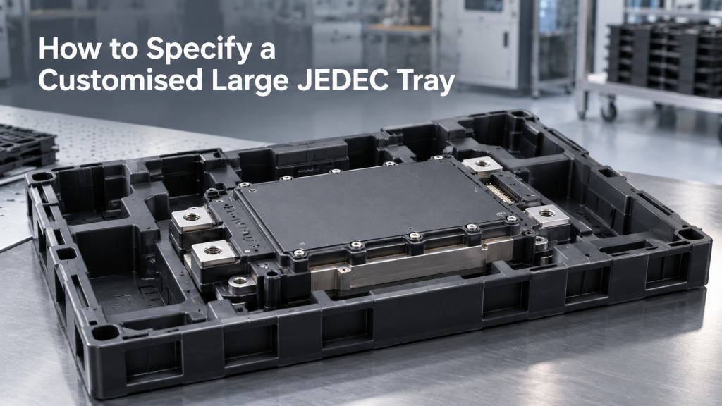
A customised big-size JEDEC tray should be designed around the component, process conditions and handling equipment, not around tray dimensions alone. The first decision is whether the application needs custom pockets within a recognised tray interface or a larger outer format that requires separate equipment validation.
This distinction matters as semiconductor production continues to expand. According to WSTS full-year 2025 market data, global semiconductor sales reached US$795.6 billion in 2025, up 26.2% from 2024, while sales in Asia Pacific and All Others increased by 45.4%.
Singapore is a significant part of this production environment. Singapore EDB reports that the country accounts for about 10% of global semiconductor output, 5% of global wafer fabrication capacity and 20% of global semiconductor equipment production.
At SuperPak, we approach a large-tray project as a component-handling and process-integration exercise. The tray must protect the part, present it consistently and work within the customer’s actual production and logistics flow.
Quick Summary
A customised big-size JEDEC tray is an engineered component carrier for oversized, tall or irregular semiconductor devices, modules or assemblies that do not fit standard pockets. Use one when the part must remain oriented, ESD-protected and compatible with handling equipment. Start by defining component geometry, support zones, ESD class, process temperature and equipment interfaces. An oversized outer footprint may not be JEDEC-compatible unless separately validated.
The practical specification sequence is:
- Define the maximum component envelope and tolerances.
- Mark permitted support areas and prohibited contact areas.
- Confirm the required ESD, temperature and cleanliness performance.
- Choose between a recognised outer interface and a custom large format.
- Prototype and validate the loaded tray before releasing production tooling.
IEC 60286-5:2018 defines common matrix-tray dimensions, tolerances and characteristics needed for automatic handling, and distinguishes trays that follow its design rules from non-standard formats.
The term “JEDEC” should therefore describe a verified interface or registered design requirement. It should not be used as a generic name for every pocketed electronics tray.
What Is a Customised Large JEDEC Tray?
A customised big-size JEDEC tray is a matrix-style component carrier whose pockets, depth, support features or outer format have been engineered for a specific device or assembly. It can retain a recognised handling interface, or it can use a fully custom footprint that must be qualified with the customer’s equipment.
A matrix tray holds multiple components in defined rows and columns. Common tray characteristics exist so that components can be loaded, stored, picked and removed consistently by manual or automated processes.
“Big size” can refer to several different requirements:
| Term | What is larger | Why it matters |
| Large component | Component length or width | Fewer pockets may fit within the available tray area |
| Tall component | Component height or protrusion | A deeper pocket or higher tray profile may be required |
| Large pocket clearance | Space around the component | Pick access and tolerance must be balanced against movement |
| High-capacity tray | Number of components per tray | Tray stiffness, weight and operator handling become important |
| Oversized outer tray | Overall length or width | Equipment, racks, cartons and load ports may require modification |
| Large-format stack | Total loaded stack dimensions | Stability, sensing and automated transfer must be validated |
A custom pocket is the cavity that supports and locates the component. The pocket may include ledges, ribs, lead clearances, orientation features, finger access and robotic pick access.
A high-profile or deep-pocket tray accommodates additional component height while retaining other controlled interfaces where possible. A fully oversized tray changes the outer envelope and may also change the stacking, transport and equipment-contact features.
SuperPak’s published thermoforming capabilities list a maximum forming area of W600 mm by L1200 mm by H400 mm and formable sheet thicknesses from 0.16 mm to 10 mm. These figures describe manufacturing capacity, not an automatically approved finished-tray size.
The finished dimensions must still be determined by forming behaviour, wall distribution, trimming, dimensional tolerances, material properties and the customer’s process constraints.
When Do You Need a Large or Custom JEDEC Tray?
A large or custom tray is normally needed when an existing qualified tray cannot support, orient or present the component safely. Size is one trigger, but fragility, contact restrictions, temperature, ESD sensitivity and handling equipment can be equally important.
Typical applications include:
- Large semiconductor modules
- Power electronics assemblies
- Printed circuit board assemblies
- Tall integrated circuit packages
- Components with connectors or protruding features
- Optical or cosmetic parts with restricted contact areas
- Components with fragile leads
- Multi-component kits requiring a fixed layout
- Work-in-progress movement between production stages
- Assemblies that must be presented consistently to inspection equipment
A custom design should be considered when a component tilts, rotates or moves excessively in an existing pocket. It may also be needed when a standard pocket touches leads, connectors, optical surfaces or other areas that the component owner has designated as no-contact zones.
Another trigger is avoidable repacking. When a component must be transferred repeatedly between temporary carriers, each transfer introduces another handling step. A tray that supports several approved process stages may simplify the flow, provided its material and geometry are suitable for every stage.
A custom tray may not be necessary when an existing qualified design already meets the component and equipment requirements. An insert may also be sufficient when only local support needs to change.
For smaller components intended for continuous automated feeding, tape-and-reel may be more appropriate. SuperPak’s published carrier-tape specifications cover widths from 8 mm to 104 mm and a maximum formable depth of 25 mm, so parts outside the practical tape envelope should be reviewed for tray or alternative packaging.
Our tape-and-reel versus tray guide provides a broader comparison of those formats.
A useful decision question is:
Can the existing packaging hold the maximum-size component, protect every restricted surface and present the part correctly throughout the approved handling route?
When the answer is uncertain, part-fit analysis and a production-representative trial should take place before the packaging format is approved.
Can a Big-Size Tray Still Be JEDEC-Compatible?
A big-size tray can be JEDEC-compatible when its controlled dimensions and interfaces follow the applicable JEDEC design requirements. A large tray should not be called JEDEC-compatible merely because it has pockets, stacking features or an appearance similar to a matrix tray.
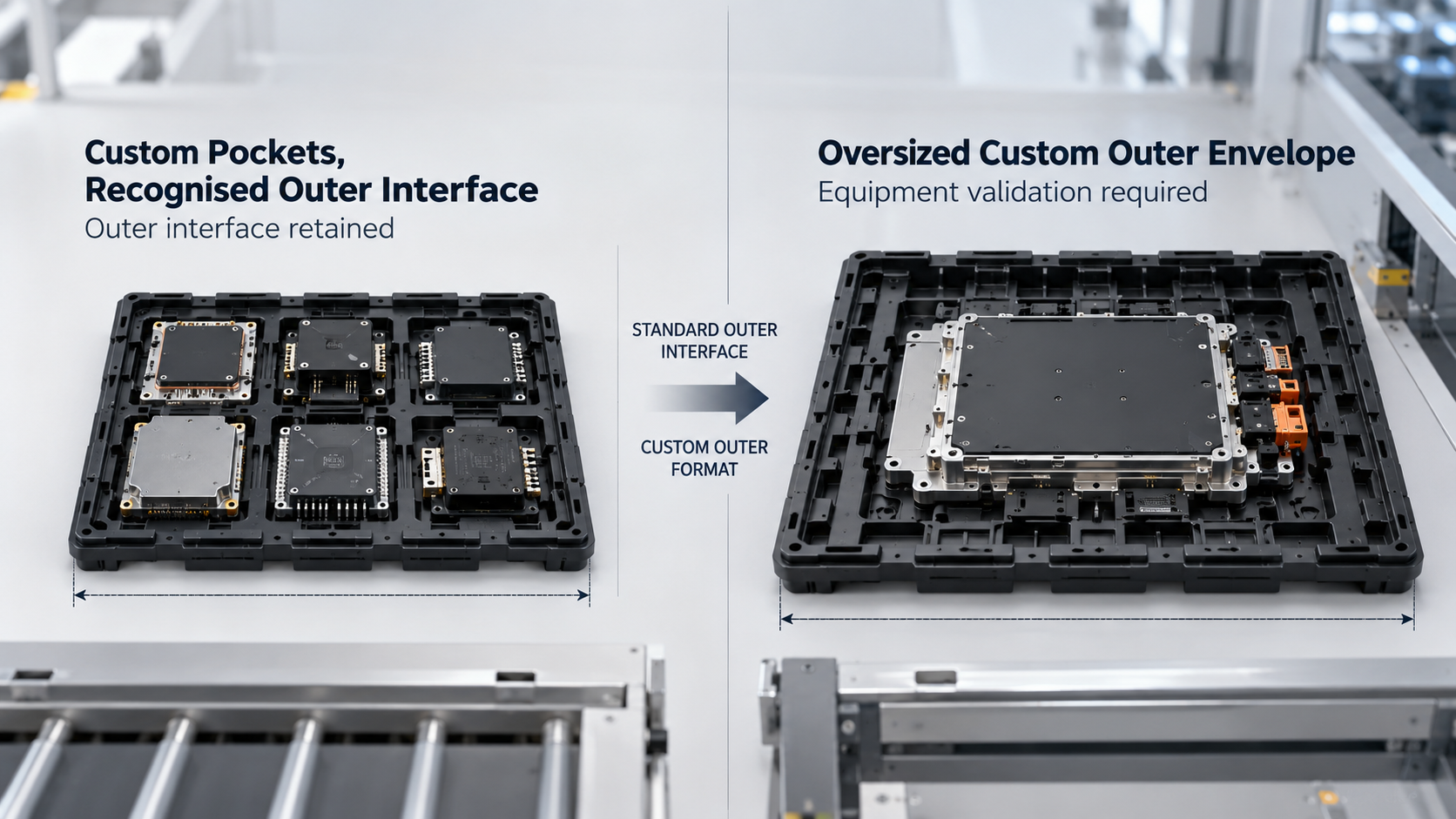
There are two principal design paths. The first customises the pocket layout while preserving a recognised outer interface. The second changes the outer envelope and requires validation against the applicable large-tray standard or the customer’s own equipment specification.
The correct compliance statement should identify:
- The applicable design requirement or registered outline
- The drawing revision used
- The dimensions and interfaces controlled by that requirement
- The features that remain customer-specific
- The inspection or equipment evidence supporting compatibility
Custom pockets within a standard outer interface
A tray can use component-specific pockets while preserving a recognised outer handling interface. This is often the lower-integration-risk route when existing equipment already depends on the tray’s outer dimensions, stacking surfaces and orientation features.
In this architecture, the controlled external area remains unchanged while the usable internal area is redesigned. The new pocket layout may change:
- Pocket length, width and depth
- Number of rows and columns
- Component support ledges
- Lead and connector clearances
- Orientation features
- Pick-up access
- Finger access
- Pocket identification
Retaining the outer interface does not remove the need for validation. The tray profile, loaded clearance, flatness, dimensional tolerances and stack behaviour can still affect equipment performance.
A controlled CAD overlay should distinguish three categories:
- Standard-controlled external features
- Customer-controlled component features
- Custom packaging features developed for the application
Our part-fit analysis and simulation testing uses three-dimensional modelling, technical drawings and dimensional verification to assess packaging fit and functionality.
Oversized outer envelope
An oversized outer envelope should be treated as a separately controlled interface unless an applicable large-tray specification covers the design. Its compatibility must be demonstrated across the equipment, storage and logistics systems that will handle it.
A large outer format can affect the full handling chain, including:
- Load ports, tray elevators and conveyors
- Robot reach, pick coordinates, vision systems and sensors
- Ovens, washers and other process equipment
- Storage racks, stack covers, cartons and pallets
- Operator lifting and carrying
Large outer formats are not automatically non-standard. SEMI E200-0626 defines dimensional requirements for a load port that accommodates Bx large trays specified by JEDEC DR4.10.
The important caveat is that SEMI E200 covers the specified load-port interface. It does not make every arbitrary oversized tray compatible with JEDEC equipment.
Where the proposed tray does not follow an applicable registered format, accurate wording includes:
- Custom large-format component tray
- Custom matrix-style tray
- Oversized thermoformed electronics tray
- Customer-specific automated handling tray
“JEDEC-style” should not be substituted for verified compatibility because the phrase does not identify which dimensions or interfaces have been controlled.
The table below condenses the practical trade-off between preserving a recognised outer interface and moving to a fully custom large-format tray.
| Decision factor | Custom pockets, recognised outer interface | Oversized custom thermoformed tray | Required verification |
| Primary goal | Fit a unique component while retaining an established handling interface | Carry a component or assembly that cannot fit within the available standard area | Confirm maximum component envelope and support zones |
| Outer footprint | Controlled to the applicable tray requirement | Defined by the component and handling system | Check loaders, racks, conveyors, ovens, washers and cartons |
| Internal pockets | Customised within the available design area | Customised across a larger tray area | Run CAD part-fit analysis and physical loading tests |
| Automation compatibility | Potentially compatible, subject to dimensional and profile checks | Not assumed unless an applicable large-tray interface is followed | Conduct loading, sensing, pick and unload trials |
| Capacity per tray | Limited by the available internal area | Can be optimised around part size and handling limits | Verify stiffness, loaded weight and stack loads |
| Manufacturing route | Selected according to geometry, tolerance, material and quantity | Often compatible with large-format thermoforming when requirements permit | Validate forming behaviour and finished dimensions |
| Stacking | Must preserve the applicable stack interface | Requires a custom stack design | Test loaded and empty stack stability |
| Compliance wording | State the applicable verified interface | State the applicable Bx requirement or describe it as custom large-format | Obtain engineering and quality approval |
| Best suited to | Existing automated tray-based production | Large modules, assemblies and non-standard process flows | Complete an end-to-end line review |
How should the correct path be chosen?
Choose a recognised outer interface when existing automation compatibility is essential and the component can be supported within the available internal design area. Choose a larger custom format when the component envelope, support geometry or required tray capacity cannot be achieved safely inside that area.
Use this three-question review:
- Must the tray pass through existing JEDEC-based equipment?
Document every loader, conveyor, oven, washer, robot and storage interface. - Can the maximum component envelope fit within the usable pocket area?
Include dimensional tolerance, protrusions, warpage and removal clearance. - Can the required support and protection features be achieved?
Confirm no-contact areas, pick access, stack clearance and tray stiffness.
When any answer remains uncertain, complete a CAD interface study and equipment trial before approving the architecture.
What Information Is Needed to Specify the Tray?
A usable tray specification needs the controlled component drawing, restricted contact areas, handling route and environmental requirements. Nominal length, width and height alone are not sufficient for a dependable design.
The enquiry should contain three groups of information.
Component data
- Controlled drawing number and revision
- Three-dimensional CAD model, where available
- Maximum component length, width and height
- Dimensional tolerances
- Component weight
- Centre of gravity
- Expected component warpage
- Leads, connectors and protrusions
- Flexible or movable features
- Permitted support zones
- Prohibited contact zones
- Required orientation
- Pick-up or gripping area
- Optical, cosmetic or functional surfaces
- Component identification method
Use maximum material dimensions and worst-case tolerance conditions for the initial fit review. Designing only around a nominal sample can result in pockets that bind larger production parts.
Process data
- Purpose of the tray
- Manual, robotic or mixed handling
- Production stages using the tray
- Equipment manufacturer and model
- Equipment-interface drawings
- Storage conditions
- Transport conditions
- Maximum temperature
- Exposure duration
- Number of expected temperature cycles
- Washing or chemical exposure
- ESD control programme
- Required packaging properties
- Cleanroom or contamination-control requirements
- Reuse expectations
- Inspection and test methods
IEC 61340-5-1:2024 sets administrative and technical requirements for establishing, implementing and maintaining an ESD control programme.
IEC 61340-5-3:2022 defines protective packaging properties for ESD-sensitive devices across production, rework, transport and storage, with referenced test methods and performance limits.
Commercial and logistics data
- Prototype quantity
- Expected production quantity
- Forecast order frequency
- Preferred parts per tray
- Maximum loaded-tray weight
- Required stack height
- Carton dimensions
- Rack and shelf restrictions
- Pallet restrictions
- Returnable-loop requirements
- Labelling and barcode fields
- Drawing and material traceability
- Delivery location
- Target implementation date
The first quotation should identify missing inputs and state assumptions explicitly. Unknown equipment interfaces, temperatures or ESD requirements should be listed as open items rather than silently estimated.
Contact Superpak to review your component drawing, physical sample, process route and equipment constraints before the tray architecture is fixed.
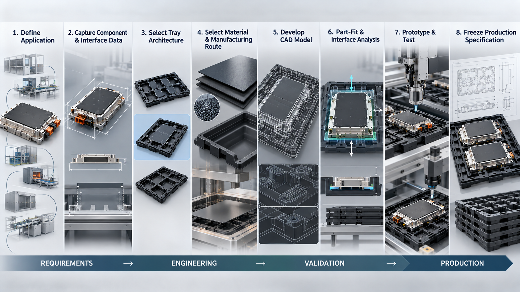
How Is a Custom Large JEDEC Tray Designed and Qualified?
A custom large tray should move through controlled design gates, beginning with requirements capture and ending with documented production approval. Production tooling should not be released until the critical component, stack and equipment risks have been assessed.
At SuperPak, our Design Center supports conceptual design, material selection and the development of thermoformed and tape-and-reel packaging.
Step 1: Define the application
The first step is to define what the tray must do and where it will be used. Document the process entry and exit points, production stages, manual and automated handling, storage, transport, cleaning or reuse loops, and ownership at each stage.
This process map prevents a design from being optimised for one workstation while failing at the next.
Step 2: Capture component and interface data
Place the component envelope and equipment interfaces under document control before detailed pocket design begins. Confirm the controlled two-dimensional drawing, three-dimensional model, representative samples, maximum tolerance conditions, support and no-contact zones, pick-up areas, equipment drawings, existing tray samples and required standard references.
Samples can support measurement and observation, but they should not replace the approved component drawing. Any difference between the drawing and the physical sample should be resolved before tooling approval.
Step 3: Select the tray architecture
The architecture determines which dimensions remain standard-controlled and which become customer-specific. It also affects tooling, equipment integration, logistics and future design changes.
The main options are:
- Custom pockets within a recognised outer interface
- High-profile or deep-pocket tray
- Bx large-tray architecture where applicable
- Fully customised oversized tray
- Multi-part kit tray
- Universal or adjustable pocket concept
- Tray with separate insert
- Tray and protective cover assembly
The design review should record why the selected architecture was preferred and which alternatives were rejected.
Step 4: Select the material and manufacturing route
Material selection must reflect the tray’s electrical, thermal, mechanical and cleanliness requirements. The manufacturing route must then be capable of producing the required geometry and tolerances consistently.
Review:
- Required ESD function
- Maximum and continuous temperature
- Number of thermal cycles
- Dimensional stability
- Stiffness
- Impact requirements
- Cleanliness
- Chemical compatibility
- Washability
- Reuse expectations
- Material traceability
- Recycling route
- Expected production volume
Our thermoformed products service includes vacuum forming, pressure forming, die cutting, CNC machining, barcoding and assembly for electronics, semiconductor and other applications.
Material names alone do not prove performance. The final grade, formulation, thickness and test condition should be stated in the approved specification.
Step 5: Develop the CAD model
The CAD model converts the component and process requirements into controllable geometry. It should represent the maximum component condition, not only an ideal nominal model.
The model should define:
- Component support points
- Pocket clearances
- Lead and connector relief
- Orientation control
- Gripper or nozzle access
- Finger access
- Sensor windows
- Stacking surfaces
- Load-transfer paths
- De-nesting features
- Label and barcode areas
- Drawing identification
- Critical dimensions
Cross-sectional views are particularly useful because they reveal vertical interference, loaded-stack clearance and wall-thickness risks that may not be obvious in a top view.
Step 6: Run part-fit and interface analysis
Part-fit analysis should check whether the full tolerance range can be loaded, supported and removed without unacceptable interference or movement. Interface analysis should check whether the tray can move through the equipment and stack as intended.
The review should examine:
- Component-to-pocket clearance
- Tilt and rotation
- Support stability
- Lead and connector clearance
- Pick-up access
- Removal path
- Loaded-tray clearance
- Tray-to-tray contact
- Stack alignment
- Equipment interference
- Sensor visibility
- Robot reach and coordinates
SuperPak’s part-fit and testing service uses three-dimensional modelling and dimensional verification, and its in-process inspection system generates measurement reports with statistical data and graphs.
Step 7: Build and test prototypes
A prototype turns design assumptions into observable results. Evaluate production-representative samples with actual components and representative equipment wherever possible, covering component fit, loading and removal, loaded and empty stacking, pick-and-place access, sensing and any applicable ESD, thermal, cleanliness or transport requirements.
Record results against predefined pass and fail criteria before production tooling is released. The detailed equipment trial sequence is covered later in the handling-equipment validation section.
Step 8: Freeze the production specification
Production release should establish exactly what will be made, inspected and controlled. It should also define how future changes will be reviewed.
The released package should include:
- Approved drawing revision
- Approved material grade
- Approved manufacturing route
- Critical-to-quality dimensions
- Inspection method
- Sampling plan
- ESD test method and acceptance criteria
- Thermal test condition
- Cleanliness requirements
- Approved markings
- Packaging and transport method
- First-article approval
- Equipment acceptance record
- Change-control procedure
A production sample should be compared with the approved prototype before volume manufacturing begins.
How Should the Pockets, Supports and Stacking Features Be Engineered?
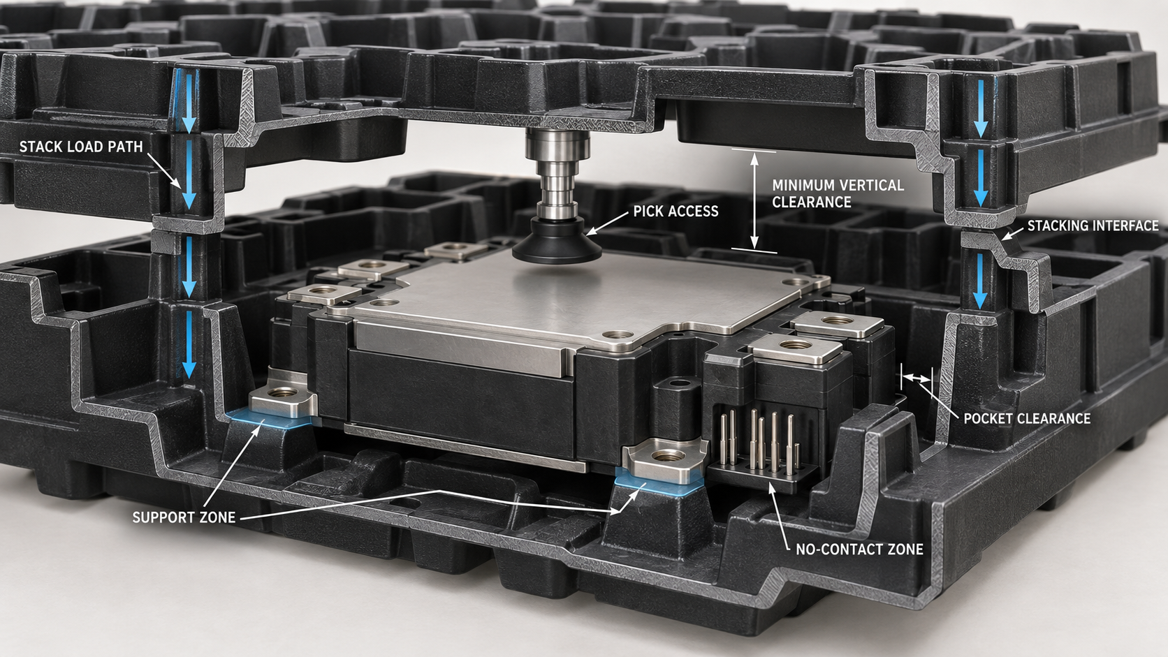
Pocket geometry should restrain the component without loading fragile or functional areas. The tray must also permit practical loading, removal, automated picking and stable stacking under the expected process conditions.
The first design task is to establish where the tray may touch the component. Suitable support areas are generally stable structural regions identified by the component owner, while leads, connectors, optical surfaces, seals and cosmetic faces may require clearance.
Component support
Support geometry should:
- Locate the component consistently
- Carry its weight through approved areas
- Prevent tipping
- Avoid concentrated force on fragile features
- Allow for dimensional tolerance
- Accommodate expected warpage
- Remain accessible for inspection
The number and position of supports should be sufficient for stability without unnecessarily increasing contact.
Pocket clearance
Pocket clearance has competing objectives. Too little clearance can cause binding, while too much can allow rotation, impact or inconsistent pick position.
The clearance study should consider:
- Maximum component size
- Minimum pocket size
- Forming or moulding tolerance
- Thermal dimensional change
- Component warpage
- Loading angle
- Removal path
- Acceptable lateral movement
The drawing should define which clearance is critical and where it is measured.
Orientation and error prevention
Asymmetric pocket geometry can reduce incorrect loading when the component itself has a clear orientation. Visual indicators can support operators and inspection systems.
Useful features include:
- Chamfered or keyed pocket corner
- Pin-one indicator
- Moulded arrow
- Row and column references
- Contrasting label area
- Tray orientation marking
- Pocket identification
These features should remain visible when trays are loaded and stacked.
Pick and removal access
Automated and manual access should be reviewed separately. A pocket that provides finger access may still obstruct a vacuum nozzle or robotic gripper.
Check:
- Nozzle diameter and approach
- Vacuum pick surface
- Gripper jaw clearance
- Robot approach angle
- Sensor line of sight
- Finger recess
- Tool-assisted removal
- Component escape path
Stacking and de-nesting
Stacking features must protect the component and transfer stack loads through the tray structure. Loaded components should not contact the tray above unless the design explicitly requires and validates that contact.
Review:
- Loaded vertical clearance
- Empty stack alignment
- Loaded stack alignment
- Stack compression
- Load-transfer surfaces
- Tray-to-tray locking
- De-nesting force
- Top-cover arrangement
- Maximum approved stack height
An annotated section drawing should show the loaded component, upper tray, minimum vertical clearance and load-transfer path.
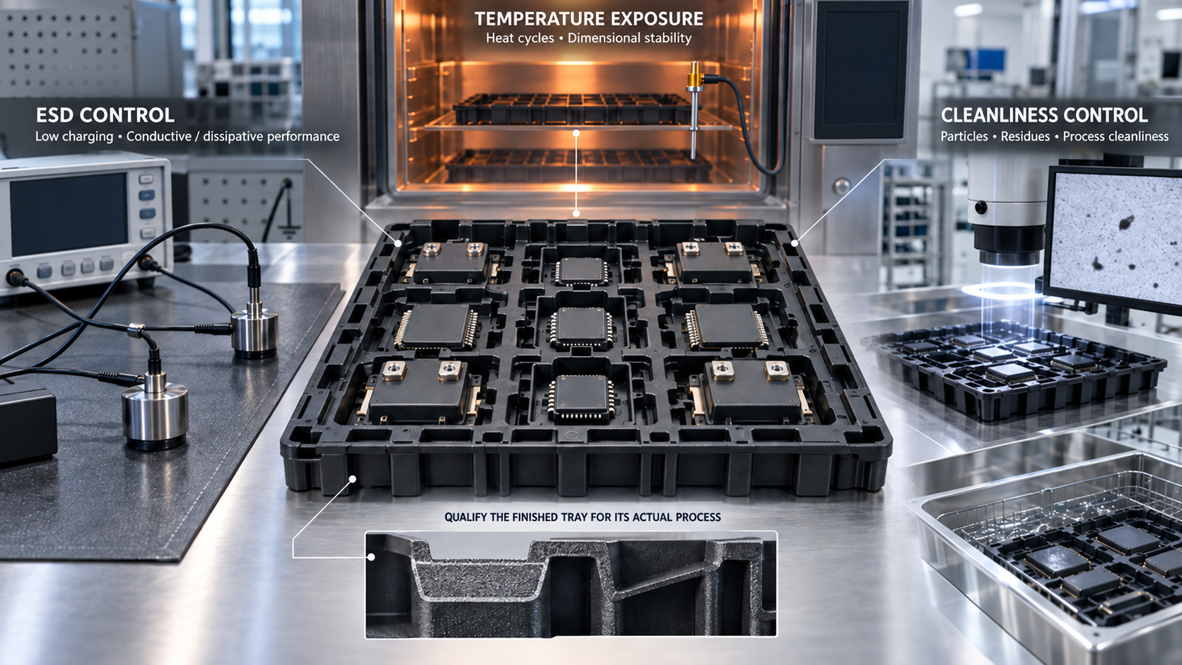
How Do ESD, Temperature and Cleanliness Affect the Design?
Material selection cannot be separated from the operating environment. A tray should be qualified for a defined ESD function, temperature profile, dimensional-stability requirement and cleanliness specification rather than described only as “anti-static” or “high temperature”.
The same base polymer can behave differently when its grade, additive system, thickness, forming process or conditioning changes. Qualification should therefore apply to the actual production material and finished tray.
What ESD performance is required?
The required ESD properties should come from the customer’s ESD control programme and packaging risk assessment. Low charging, conductive or dissipative resistance and discharge shielding are different functions and should not be treated as interchangeable.
Inside an electrostatic protected area, packaging or handling containers should provide the low-charging and conductive or dissipative properties required by the applicable programme. Outside that protected area, discharge shielding may also be required, as explained in the ESD Association’s packaging guidance.
ANSI/ESD S541-2026 defines packaging properties for protecting ESD-susceptible items throughout production, transport and storage.
The tray specification should identify:
- Applicable ESD standard and revision
- Required packaging function
- Test method
- Conditioning method
- Test location
- Acceptance limit
- Sampling frequency
- Lot traceability
- Requalification interval
- Requirements after washing or heat exposure
Resistance alone does not predict low-charging behaviour, so a resistance result should not be presented as proof of every ESD property. The ESD Association’s guidance distinguishes these protective functions.
Avoid relying on the words “ESD-safe” without supporting test data.
What temperature must the tray withstand?
Specify the actual temperature profile, exposure duration and number of cycles rather than requesting a generic heat-resistant tray. Qualification should assess whether the finished tray remains dimensionally and electrically suitable after the intended process.
Provide:
- Maximum temperature
- Continuous operating temperature
- Heating rate
- Exposure duration
- Number of cycles
- Loaded or unloaded condition
- Cooling method
- Oven support arrangement
- Chemical or humidity exposure
- Post-process dimensional criteria
- Post-process ESD criteria
A short high-temperature exposure and a long production bake can create different risks. The test condition should therefore reproduce the intended use as closely as practical.
Check critical pocket dimensions before and after thermal exposure. Repeat the component-fit and stacking review if dimensional change could affect handling.
What cleanliness level is needed?
Cleanliness requirements should be defined by the process in which the tray will be used. Cleanroom classification, tray-surface cleanliness and chemical residue are separate controls that may require different test methods.
ISO 14644-1:2015 classifies cleanroom air cleanliness by airborne-particle concentration, but it does not characterise the particles’ physical, chemical or viable nature.
A complete tray-cleanliness brief may include:
- Required cleanroom classification
- Permitted particle level
- Ionic contamination limits
- Organic residue requirements
- Prohibited mould-release residue
- Outgassing requirement
- Cleaning chemistry
- Rinse-water quality
- Drying method
- Clean packaging after washing
- Sampling and laboratory methods
- Reuse and rejection criteria
SuperPak’s published collection and washing capabilities list 3 aqueous washing machines with built-in vacuum ovens, 1 dedicated tray washer, a deionised-water plant, an in-house laboratory and Class 1000 washing lines. The same facilities page lists ion chromatography, liquid-particle counting, FTIR, UV spectrophotometry and ultrasonic equipment for contamination assessment.
A tray that looks clean may still fail a customer’s ionic, particle or ESD specification. Reuse approval should therefore be based on the agreed inspection and test criteria.
Our guide to custom JEDEC tray washing and cleaning explains how inspection, cleaning, drying and verification can be structured for a returnable tray loop.
Contact Superpak to align your tray material, ESD, temperature and cleanliness requirements with a testable specification.
How Should a Large Tray Be Validated on Handling Equipment?
A dimensional inspection alone cannot prove that a large tray will work on production equipment. A production-representative tray should be tested through loading, sensing, stacking, picking, unloading and fault recovery on the actual equipment wherever possible.
The equipment inventory should cover every relevant interface:
- Tray loader
- Load port
- Tray elevator
- Conveyor
- Robot
- Pick-and-place head
- Vacuum nozzle
- Gripper
- Vision system
- Presence sensor
- Orientation sensor
- Oven
- Washer
- Storage rack
- Carton
- Pallet
SEMI E200-0626 addresses a uniform physical load-port interface for the automated delivery and pickup of Bx large JEDEC tray stacks.
That interface is only one part of qualification. The component must also remain correctly presented inside the tray.
A practical validation sequence is:
- Load one empty tray.
- Load an empty tray stack.
- Load one component-filled tray.
- Load a representative filled stack.
- Confirm sensor detection.
- Confirm tray orientation.
- Run pick and placement.
- Run tray changeover.
- Observe stacking and de-stacking.
- Test a controlled stop and recovery.
- Repeat representative production cycles.
- Inspect the tray and components after testing.
Acceptance criteria should include:
| Test area | Example acceptance requirement |
| Mechanical loading | No interference or forced insertion |
| Sensor performance | Reliable detection in the approved orientations |
| Component presentation | Stable and repeatable pick position |
| Robotic access | No collision with pocket or tray features |
| Stacking | No unacceptable tilt, locking or collapse |
| Thermal equipment | No interference or unacceptable deformation |
| Operator handling | Safe grip, weight and movement |
| Fault recovery | Tray and components remain recoverable without damage |
The equipment trial should record the tray revision, material, loaded component, machine identification, software recipe and test result. Photographs or video can supplement the signed engineering record.
What Affects the Cost, Tooling and Lead Time?
Cost and lead time depend on tray size, pocket complexity, material, tooling route, test scope, production quantity and prototype iterations. A responsible quotation should separate these variables and state the assumptions used.
Design and tooling drivers
- Number and complexity of pockets
- Deep features
- Tight radii
- Restricted draw areas
- Critical tolerances
- Stack geometry
- Nozzle or gripper access
- Universal or multi-SKU requirements
- Insert or cover requirements
- Prototype tooling route
- Production tooling route
Material drivers
- Sheet thickness
- ESD additive system
- Temperature capability
- Dimensional stability
- Cleanliness requirements
- Chemical resistance
- Washability
- Colour
- Traceability
- Minimum material purchase quantity
Qualification drivers
- CAD part-fit study
- Tolerance analysis
- Prototype rounds
- Dimensional inspection
- ESD testing
- Thermal testing
- Cleanliness testing
- Equipment trials
- Transport testing
- First-article documentation
Production and logistics drivers
- Order quantity
- Production frequency
- CNC machining or secondary trimming
- Labelling and barcoding
- Cleaning
- Clean packaging
- Carton and pallet design
- Regional delivery
- Returnable-loop management
- Storage and warehousing
A quote-comparison table should separate the following costs:
| Cost category | What the quotation should state |
| Engineering | Design scope, included revisions and deliverables |
| Prototype tooling | Tool type, expected use and ownership |
| Samples | Quantity, material and inspection scope |
| Production tooling | Tool construction, maintenance and ownership |
| Production trays | Quantity breaks and included secondary operations |
| Testing | Test method, laboratory and number of samples |
| Documentation | Inspection reports, certificates and traceability |
| Logistics | Packing, freight, delivery term and storage |
| Changes | Charges for drawing, material or tooling revisions |
Price per tray should not be evaluated alone. A lower unit price may exclude tooling, testing, cleaning, secondary operations or delivery that another quotation includes.
What Mistakes Cause Custom Large-Tray Projects to Fail?
Most custom-tray failures begin before production tooling is built. Incomplete component data, vague compliance wording, ignored equipment interfaces and skipped prototype testing create avoidable risk.
| Mistake | Likely consequence | Prevention |
| Requesting a “large JEDEC tray” without identifying which dimension is large | Different teams work to different requirements | State the component, pocket, profile and outer-envelope needs separately |
| Calling every electronics tray JEDEC-compliant | Misleading specification or equipment mismatch | Identify the exact controlled interface and applicable design requirement |
| Designing from nominal dimensions | Larger production components may bind | Use the maximum component envelope and tolerances |
| Ignoring no-contact areas | Damage, contamination or cosmetic defects | Mark permitted and prohibited support zones |
| Using one physical sample as the complete specification | Production variation is not represented | Reconcile samples with the controlled drawing |
| Selecting material by a generic temperature label | Warpage or property change after real exposure | Test the actual time and temperature profile |
| Treating “anti-static” as a full ESD requirement | Unverifiable or insufficient protection | Specify function, test method and acceptance limit |
| Ignoring loaded-stack behaviour | Component contact or unstable stacks | Test production-representative loaded stacks |
| Checking dimensions but not equipment operation | Jams, sensor faults or failed picks | Run loading, sensing, picking and recovery trials |
| Freezing tooling before prototype approval | Expensive redesign | Use gated prototype and first-article approval |
| Omitting change control | Unapproved production variation | Freeze drawing, material and critical dimensions |
| Reusing trays without requalification | Degraded fit, ESD or cleanliness performance | Establish inspection, testing and rejection rules |
A further mistake is combining requirements from different standards without identifying which one controls each feature. IEC 60286-5:2018 addresses matrix trays, IEC 61340-5-3:2022 addresses ESD protective packaging, ISO 14644-1:2015 addresses cleanroom air classification, and SEMI E200-0626 addresses the Bx large-tray load-port interface.
The design record should map each requirement to its source, verification method and acceptance evidence.
How Do You Start a Custom Large-Tray Project with SuperPak?
Start by sharing the controlled component information, intended process route, equipment constraints and environmental requirements. We can then assess the feasible tray architecture, material route, prototype scope and validation plan.
SuperPak was founded in Singapore in 1985 and provides design, manufacturing, supply-chain, kitting, logistics and warehousing services.
Singapore EDB reported in May 2026 that more than S$30 billion was invested in the country’s semiconductor sector from 2022 to 2025. EDB also reports that the sector accounts for nearly 6% of Singapore’s GDP and employs more than 35,000 people.
Minimum enquiry pack
A useful first submission gives our engineering team enough information to identify major risks and avoid assumptions. Please provide:
- Controlled component drawing or three-dimensional model, plus representative physical samples where available
- Maximum dimensions, tolerances, weight, support zones, no-contact areas, orientation and pick-up requirements
- Existing tray or packaging samples, required tray capacity and process-flow description
- Equipment list and relevant equipment-interface drawings
- ESD, temperature, cleanliness, washing and reuse requirements
- Prototype quantity, forecast production quantity, delivery location and target implementation date
Where a requirement is not yet known, label it as “to be confirmed”. This is preferable to entering an assumed value that may later be treated as approved.
What SuperPak should return
Our initial response should make the proposed design path and its assumptions clear. The exact deliverables depend on the information supplied and the project’s qualification needs.
A feasibility response may include:
- Clarification questions
- Recommended tray architecture
- Initial material direction
- Proposed manufacturing route
- Applicable interface assumptions
- Identified technical risks
- Prototype recommendation
- Test and qualification scope
- Commercial quotation
- Indicative project stages
- Customer approvals required
- Information still outstanding
For supplier qualification and change-control planning, our ISO 9001 semiconductor packaging guide provides a checklist for reviewing scope, site, evidence and pilot production.
Contact Superpak to request a feasibility review and quotation for your customised big-size JEDEC or large-format component tray.
Frequently Asked Questions About Customised Big-Size JEDEC Trays
Can a tray be oversized and still be JEDEC-compatible?
Yes, provided the relevant dimensions and interfaces comply with an applicable design requirement. For example, SEMI E200-0626 specifically addresses load ports for Bx large trays specified by JEDEC DR4.10.
A customer-specific footprint outside an applicable design requirement should be described as a custom large-format tray until its interfaces have been documented and validated.
Which material is best for a large JEDEC or electronics tray?
There is no universal best material. Selection depends on the required ESD function, temperature profile, dimensional stability, cleanliness, tray size, manufacturing route and expected reuse.
The final material specification should identify the exact grade, thickness and required tests. A general polymer name or “ESD-safe” description does not provide enough information for qualification.
Can large custom trays be cleaned and reused?
They can be cleaned and reused when the material, dimensions, stacking features and ESD properties continue to meet the approved specification. The reuse programme should define inspection, washing, testing, traceability and rejection criteria.
Trays with cracks, unacceptable warpage, damaged stacking features or failed electrical properties should be removed from the reuse loop. Cleanliness and ESD performance should be verified according to the customer’s defined methods rather than judged only by visual appearance.